Chassis & drivetrain. Sources & assumptions.
The real E16 sets the silhouette. The rules explain the structural logic. The hidden details remain a declared reconstruction.
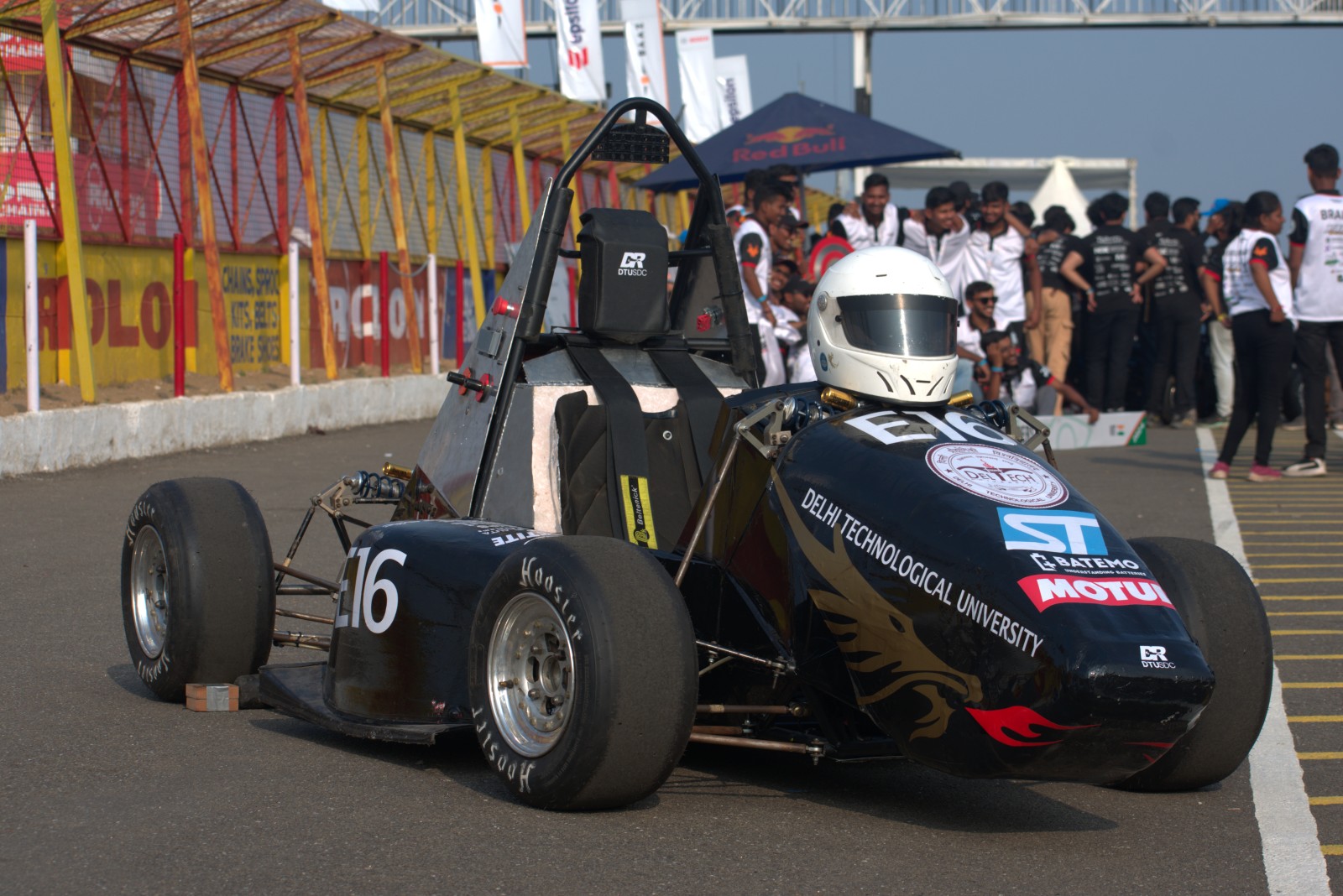
The 2024 E16.
The visual anchor.
The black-and-gold nose, rounded triangular hoop, silver firewall, blue springs, perforated wheels and wingless layout are visible in the team’s photograph. Earlier E07 photographs help explain the exposed frame and rear braces.
The model adds a coherent internal layout so it can be taken apart. Tube placement, scale, electronics, cooling and powertrain internals are inferred.
A tube is more than its diameter.
Meets the three selected nominal section thresholds.
Minima: t ≥ 2 mm · A ≥ 173 mm² · I ≥ 11320 mm⁴. This checks ideal section arithmetic only, not material, joints, tolerances or structural compliance.
Two hoops.
Connected load paths.
- Roll hoops. Continuous bent members protect the cockpit. The current rules require a bend centerline radius of at least three outside diameters. The model’s hoop silhouette is photo-inspired; its curvature has not been certified.
- Main-hoop braces. The paired rear braces attach near the top and return into the rear frame. FB2027 specifies attachment within 160 mm of the top and an included angle of at least 30°.
- Side impact. Upper and lower rails plus node-to-node diagonals triangulate each cockpit side. The upper member’s vertical band is 240–320 mm above the lowest inside chassis point.
- Front bulkhead. A forward frame, support triangles, anti-intrusion plate and impact attenuator are separate parts beneath the nose.
Current references: T3.7 p46; T3.10–11 p48; T3.13 p49; T3.14 p50. The official PDF contains the complete conditions.
The 3D model uses a 25.4 mm visible tube diameter. Example nominal walls are 2.5 mm for hoops, 1.65 mm for impact / brace members and 1.25 mm for supports. Rendering does not assign or validate every structural section.
Mechanical assemblies.
- Four detachable corners: slick tire, perforated rim, hub and fasteners, drilled brake rotor, caliper, upright, wishbones, steering link, pushrod, rocker and coilover.
- Driver controls: steering wheel and column, rack boots, steering actuator, two pedals (brake and accelerator), dual master cylinders and an illustrative braking actuator.
- Cockpit: seat, harness, head restraint and a distinct firewall. Hardware is arranged to explain functions, not reproduce a verified installation.
TSAC & limited-slip differential.
The TSAC (tractive system accumulator container) is closed when assembled. Exploding the car lifts its lid to expose illustrative segments, insulating partitions, AMS boards and service disconnects. A separate electrical bay contains two accumulator isolation relays (AIRs), a fuse and a precharge element. Their shapes explain functions; cell format, ratings and topology are not verified E16 specifications.
Piyush confirmed the limited-slip differential and two-pedal layout. The model connects a transverse motor through a guarded reduction to a central LSD and rear half-shafts. The chain ratio and packaging remain illustrative. FB2027 EV5.5.8 requires vertical TSAC partitions to reach the lid; EV5.5.14 separates AIRs and the main fuse from cells. A distinct firewall separates the cockpit. This reconstruction does not establish electrical or crash compliance.
Compute and telemetry boxes separate sideways in the exploded view. Their function links to the planning, control and networking demonstrations, while the radiator, fan, pump and hoses explain cooling.
What you’re seeing.
Section arithmetic: A = π(D² − d²)/4 and I = π(D⁴ − d⁴)/64, with d = D − 2t. FB2027 Table 4 p42 has a 173 mm² hoop-area minimum; FS2023 Table 4 p27 has 175 mm². The selector preserves that difference.
A rounding trap: a nominal 25.4 × 1.6 mm circular tube gives I = 8508.815 mm⁴. It rounds to 8509, but lies slightly below that literal threshold. The calculator compares unrounded values.
Model boundaries: no team CAD, engineering submissions or proprietary datasets are published here. Scale, hidden joints and internal hardware are illustrative. There is no FEA, torsional-stiffness, crash, weld or scrutineering result behind this reconstruction. The team photograph remains credited to Team Defianz Racing.
Educational reconstructions of ideas from my work. Demo results are computed here; they are not team test results.